The Information window displays numerical information about selected areas of the image. The window can be switched on and off using the Information Window command on the View menu, or by using the ![]() button on the Toolbar. The window can remain open as a floating toolbox without interfering with other commands.
button on the Toolbar. The window can remain open as a floating toolbox without interfering with other commands.
The Information window has four modes of operation: Aperture, Region, Area, and Astrometric. There is also a Magnitude display that can be calibrated to show accurate stellar magnitudes. Except in Area mode, the mouse cursor will change to a crosshair and "bullseye" when the Information window is active and the mouse is over the selected image or preview. The sizes of the various elements of the circular cursor can be changed using the mouse with the right-click menu.
To lock the cursor at a specific position and freeze the information display, double-click on the image. When locked, the circular cursor can be moved using the arrow keys. You can then copy text from the status area of the Information window to the clipboard using the mouse and CTRL-C (or right-click the mouse in the status area and select Copy from the resulting context menu). To restore normal operation, click the mouse again on the image.
Numbers exceeding one million are shown in scientific notation; a lower case e followed by an integer means the preceding quantity must be multiplied by that power of ten.
Aperture
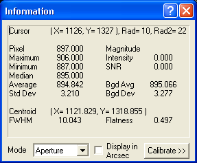
Aperture mode shows statistics on the area under the circular cursor as the mouse is moved around the image. The current Cursor position and inner and outer radii are shown at the top. The Pixel value directly under the cursor is also shown.
The following measurements are made only within the aperture (inner circle): the Maximum, Minimum, Median, Average, and standard deviation (Std Dev).
The following measurements are made inside the aperture after first subtracting the average value in the annulus (between the middle and outer circles): stellar Magnitude (as calibrated using the Calibrate button), Intensity (sum of all pixels within aperture less background), and signal-to-noise ratio (SNR). SNR is calculated as the ratio of intensity to the standard deviation of the background times the square root of the number of pixels. When measuring a star, a SNR of 3 is usually considered the minimum necessary for detection.
The following measurements are made using only the background annulus (between the middle and outer circles): background average (Bgd Avg) and background standard deviation (Bgd Dev).
The Centroid is calculated within the inner aperture. It is an indication of the ”center of gravity” of the star image, and is calculated to a fraction of a pixel. The full-width half maximum or FWHM is also calculated. This is a measurement of the diameter of the star image at ˝ of the maximum intensity. It is calculated by fitting a Gaussian shape to the star. The Flatness is an indication of how out-of-round the star image is. A flatness of zero is perfectly circular, while a flatness of 0.1 indicates that the star is longer in one dimension than the other by 10%.
When Display in Arcsec is checked, the FWHM is displayed in arc-seconds instead of pixels. The Calibrate section below describes how to set up the arc-seconds display.
Please note that the Photometry function can provide more accurate Magnitude measurements than the Information window can. The Photometry function performs more complex and accurate background subtraction computations, and uses partial pixels. In the interest of speed the Information window performs a simpler calculation.
Region
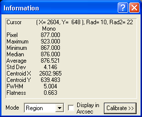
Region mode is a simpler version of the Aperture mode, which provides separate information for the Red, Green, and Blue planes of a color image.
Pixel is the value directly under the cursor center. All other measurements are calculated within the central aperture. This includes Minimum, Maximum, Median, Average, Std Dev (standard deviation), Centroid X, Centroid Y, full-width half maximum (FWHM), and Flatness. For a description of these values please see the previous section discussing the Aperture mode.
Area
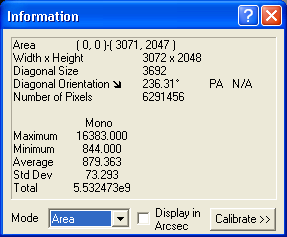
This mode displays statistics for a rectangular region of the image. The default is to show data for the entire image, but an area can be selected by holding the left mouse button down while dragging on the image. This will draw a rectangle on the image; the statistics data now applies to the region inside the rectangle. Tip: to drag a square box, hold down the ALT key.
Note that the rectangular region can be moved and resized with the mouse. Grab it with the mouse in the middle of a side to reposition it, or at a corner to resize it.
The Area is shown as the coordinates of the corners of the box, and Width x Height is shown. The Diagonal size of the box is shown, which allows you to measure distances on the frame. The Diagonal Orientation is shown graphically as an arrow and numerically in degrees; this indicates which way the mouse was dragged. If an astrometric solution is available, the Position Angle (PA) is shown (relative to true North). The total Number of Pixels included in the box is also displayed.
Statistics are shown for the pixels inside the box. Maximum and Minimum pixel values, Average pixel value, standard deviation (Std Dev), and the Total of all pixels in the rectangular region.
When Display in Arcsec is checked, the Diagonal Size is displayed in arc-seconds instead of pixels. The Calibrate section below describes how to set up the arc-seconds display.
Astrometric
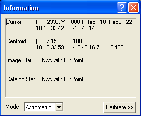
The Astrometric mode uses the included PinPoint LE (light edition) Engine, or the full edition if installed. This powerful analysis tool can be used for extremely precise measurements of star positions in the sky. Astrometric analysis works by identifying the stars in the image and matching them against an accurate catalog of star positions. The software is then able to calculate accurate positions for every object in the image. The full edition of PinPoint, available from DC-3 Dreams, provides additional capabilities, and has tools for discovering asteroids and supernovae, generating MPC reports, and more. For more information visit the DC-3 Dreams web site at http://pinpoint.dc3.com.
To display information, the image needs to have World Coordinate System (WCS) entries in the FITS header. These are added automatically during image analysis by PinPoint, but they can be obtained from other software as well.
The Information window shows the following information in Astrometric mode: Cursor X, Y pixel coordinates and annulus radii, along with the Right Ascension and Declination of the pixel under the mouse cursor. Centroid of the star under the circular cursor in both X, Y coordinates and RA, Dec; and the magnitude of the star within the aperture, as measured by MaxIm DL using the current calibration (see below).
For users with the full version of PinPoint, extra information is available after you perform a PinPoint analysis on an open image. Image Star provides the position and magnitude of the star within the aperture (that closest to the center is used if there is more than one) as determined by PinPoint. Catalog Star provides information on stars that were identified in the catalog used during analysis. This includes the identity of the star, the position, and magnitude as provided by the catalog. The table of the catalog and image stars detected in the image, which is used to display Image Star and Catalog Star information as you probe the image with the circular cursor, is not recorded when an image is saved to disk. This information is therefore not available when an image is loaded unless you re-solve the image using PinPoint Astrometry.
Calibrate
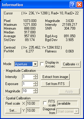
Various displays can be calibrated by clicking the Calibrate button.
Magnitude Calibration sets up the Magnitude display on the Information window. You need to enter the Intensity and known Magnitude of a star on the image, as well as the Exposure time used for the image. Once these values are known, the magnitude calibration will be accurate for any image taken with the same camera (note: some cameras have multiple modes which may affect this).
Although the magnitude for the star must be obtained from other sources, Intensity can be entered easily using the mouse. Click Extract from image and point the mouse cursor at a star in the image for which the magnitude is known. Adjust the aperture to include the entire star image. Click the mouse, and the intensity value for the star will be measured and filled in.
Click the Set from FITS button to set the Exposure. If the FITS header for the image includes exposure information (which it will if it was taken with MaxIm DL), then this information will be automatically entered. The exposure information is used to scale measured intensities so that images with different exposure lengths can be compared.
Please note that the Photometry function can provide more accurate measurements than the Information window can. The Photometry function performs more complex and accurate background subtraction computations, and uses partial pixels. In the interest of speed the Information window performs a simpler calculation.
The Spatial Calibration function is used to convert from pixel units to arc-seconds. The two Pixel Scale values shown are in arc-seconds per pixel. If FITS scale is checked, they will be set automatically from the World Coordinate System (WCS) information recorded in the FITS header by PinPoint or other astrometric analysis tools. In the absence of WCS, pixel scale is automatically calculated from the camera pixel dimensions and telescope focal length if these are available. If neither type of information is present, the small status field to the right of the FITS scale check box shows "not available" and the most recent pixel scales (possibly from some other image) are reused.
The Pixel Scale values can also be set up using the Set… button. This brings up the Pixel Scale Editor.
![]()
If the pixel scale is already in the FITS header, just select Pixel Scale and click Load from FITS. Alternatively, you can also enter values manually in the X and Y fields in this mode. The scale is in arc-seconds per pixel.
Another method is to use the Calculator mode. Enter the Pixel Size (microns) and Focal Length (mm), or click the Load from FITS button within the Calculator frame to extract the values directly from the FITS header. Most cameras supported by the Camera Control window provide pixel dimensions automatically when an image is taken, while the telescope focal length can be specified on the Site and Optics tab of the Settings dialog. The required value can often be found in the manual for your telescope, or can be determined by multiplying the aperture by the f/ratio. Click Calculate scale to compute and display the pixel scale. Then click OK to close the window and return the values to the Information Window.