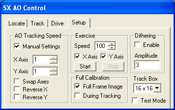
The Setup tab is used to set various AO options and to test the AO unit.

The AO Tracking Speed is the distance a star is moved (in pixels) by a 50% mirror deflection (i.e. from 50% tilt to 100% tilt) multiplied by 7. These values should be filled in using the Calibrate AO function on the Locate tab. These values may be larger if a filter wheel is installed between the AO and the camera, due to the extra distance between the AO and the detector. The X and Y values should be within a factor of two of each other.
If star drift during the AO calibration is too great, the AO Tracking Speed values may be incorrectly set. This could occur because of very poor polar alignment or periodic error. If both the X and Y directions are incorrect by the same amount, adjusting the Aggressiveness while autoguiding would compensate for the tracking speed. However if the stars on the main exposure are oval shaped, either the X or the Y (but not both) AO Tracking Speed will have to be manually adjusted (N.B. Increasing the Tracking Speed is akin to decreasing the Aggressiveness and vice versa). Calibrating using a very bright star and a very short exposure will minimize this problem. Remember that the AO calibration only needs to be done once unless the hardware is modified.
The Reverse X, Reverse Y and Swap Axes check boxes are automatically set using the Calibrate AO mode on the Locate tab. However they can be set manually if the Manual Settings check box is checked. The Swap Axes check box is turned on when the X axis of the autoguider image corresponds to the Y deflection axis of the tip/tilt mirror.
Some autoguider sensors have hot pixels which can confuse or "capture" autoguiding. In this case, you can apply image calibration to autoguider images before star detection and position measurement occur. To do this, you must first use MaxIm DL's Set Calibration command to create suitable calibration groups for the autoguider at all binnings you intend to use. Then set the Full Frame Image checkbox to enable calibration for images taken with the Locate tab. Additionally, you can set During Tracking to calibrate subframes taken by the Track tab, though this is often unnecessary and can reduce the AO tracking rate. Calibration is automatically turned off if it cannot be performed successfully.
The Track Box determines the size of the tracking image displayed on the Track tab while autoguiding. A smaller Track Box will increase the update rate but will also increase the chances that the guide star is lost due to a large instantaneous deviation. In most cases an 8x8 Track Box is a good compromise.
Enabling the Dithering option causes the AO tracking position to change by a small amount after each main chip exposure. This is used to produce a sequence of images centered on a particular location, but with each one offset by a small random amount. The maximum offset is set by Amplitude, which determines the maximum offset from the starting position. This can be larger than the track box, because the offset will not be moved by more than 1/2 of the track box size at one time.
The maximum number of pixels that the tracking position will be offset is the minimum of the Amplitude setting and one half of the size of the Track Box. For instance, if an 8x8 track box is used, and the Amplitude is set to 5, then dithering will offset each exposure by up to 4 pixels.
The Test Mode option allows you to evaluate the performance of the AO. During a test mode exposure the pane of glass in the AO will be periodically deflected from its tracking orientation to 0% x 0%(full deflection in both axes) and held for five seconds, then will return to normal guiding for five seconds. This produces an image with two sets of stars, one of which was corrected by the AO, and the other uncorrected.
The Exercise controls allow for visually checking the operation of the tip/tilt system. Remove the AO/camera combination from the telescope and look at the pane of glass controlled by the tip/tilt motors. When this function is activated, the glass pane will repeatedly move between the four extreme positions. The X Axis and/or the Y Axis can be tested independently and the time spent while stationary (in milliseconds) at each extreme can be varied with the Speed setting. All these settings can be changed while the AO is exercising.
Please note that the method used to send bump commands to the mount is selected using Guide tab Settings Control Via.